
Home / Engineering Services / Computational fluid dynamics
Computational fluid dynamics
Flow problems are expensive to find on site and cheap to find in a model. We quantify pressure drop, temperature distribution and mixing behaviour before the equipment is fabricated.
Simulation method, turbulence model and convergence criteria are set deliberately and stated in the report — not left at software defaults. More on our simulation methodology
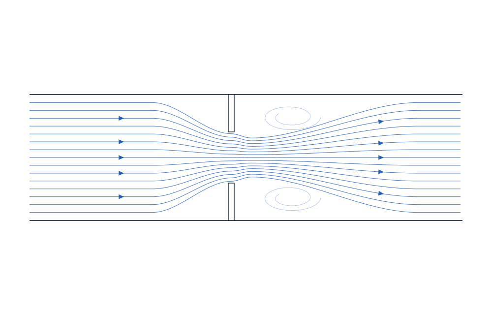
Where CFD earns its cost
A pressure drop that is 30% higher than assumed does not usually announce itself until the pump is undersized and the plant is running below rate. A dead zone in a vessel does not appear on a general arrangement drawing. A thermal short-circuit in a ducting run shows up as a performance shortfall nobody can locate.
These are the problems CFD is genuinely good at. It is less useful as decoration — a coloured picture of flow that nobody acts on is a cost with no return. We scope studies around a decision: which of these two designs, what is the real pressure drop, will this mix in the residence time available.
Typical applications
Heat exchangers and thermal equipment
Shell-side and tube-side flow distribution, effectiveness, hot spots and maldistribution. Where a unit is underperforming in service, CFD usually locates the cause faster than instrumentation.
Separators and multiphase equipment
Gas-liquid and oil-water separation behaviour, residence time, carry-over and carry-under, internals placement and baffle effectiveness.
Mixing and reaction vessels
Blend time, dead zones, impeller placement and shear distribution — including the wide, shallow digester geometries common in biogas and CBG plant.
Ducting, manifolds and flow distribution
Pressure loss through bends, orifices and manifolds, flow split across parallel paths, and ventilation or thermal management in enclosures.
What you receive
A report that leads with the number you asked for — the pressure drop, the outlet temperature, the blend time — followed by the evidence supporting it. Contour and vector plots are included where they explain something, not as filler.
Where we ran design variants, the comparison is presented side by side with the trade-off stated. Our recommendation is separated clearly from the simulation result, so you can disagree with the recommendation without discarding the analysis.
Deliverable contents
A standard CFD package includes:
- Headline performance figures against the design intent
- Geometry, mesh statistics and convergence history
- Turbulence model and solver settings with justification
- Boundary conditions and their source
- Contour, vector and streamline plots where they aid interpretation
- Design-variant comparison where applicable
- Recommendations, stated separately from results
Tell us the flow problem.
A sketch, a datasheet and the question you need answered are enough to scope a study.